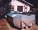
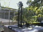
Now that the skirt is attached and the hull is painted it's time the engine stand got bolted to the
rear deck. |
|
Next it was time to mask off the hull side decks and paint the accent stripes. |
|
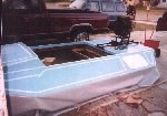
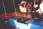
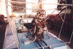
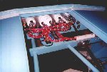
This is the forward engine stand mount and the fan bearing stack as viewed from the cockpit. |
|
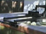
This is the rear engine stand mount. You can also see the center mounting bolt pedestals by the idler
pulleys. |
|
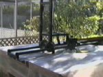
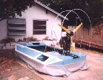
Here is an overall view of the engine stand bolted onto the rear deck, fan installed (and waiting for the engine).
|
|
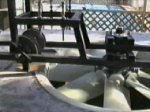
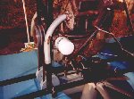
A closer detail shot of the engine riser platform, idler pulleys, fan bearing stack and the fan in the duct. The pulleys are
mounted on a fixed axle and the engine bolts shown are used to lift the entire engine up or down to adjust the fan belt tension. Fan tip clearance is approximately 5/32". |
|
Paint is almost complete and the prop guard is just beginning. |
|
I attached a small peice of steel angle to the bottom of the prop guard to attach it to themain hull stringer. |

|
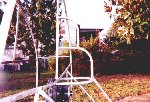
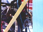
Here is the attachment point of the 3 main radius rods at the top of the engine stand. |

|
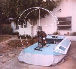
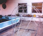
This is a good overview of the prop guard beginning to take shape. |
|
Here you see the lower rudder guard crossbar attached to the sides of the guard and the rear engine stand mount. |
|
This is the famework for the flashing yellow and anchor lights. The tubes will protect the lights somewhat from being hit with low
lying branches as well as provide structural support for the top half of the guard. |
|
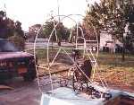
Here is the guard with all the radius rods and braces in place. |
|
Time for the wire mesh to be installed. |

|
A test fit of the guard on the rear deck. I don't remember if this was test fit number 4 or test fit number 36! |
|
A rear view of the guard installed and reay to go. |
|
The engine and fan drive components installed on the engine/drive stand and the test exhuast system installed on the engine.
|
|
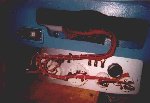
The engine and prop drive components installed with the exhaust system welded together. Note the speed sensor bar mounted to the
engine drive pulley and the pickup sensor mounted above the pulley. The tach is set up as a pulse revolution counter. |
|
The dash wiring has been started.Of course there is still many more to add before it is completed. |
|
The dash is finally wired and installed. It sure took a lot of wire ties to keep it looking like that! |
|