Here is the basic design of my new GEO engine stand. I will be using four vertical tubes to support the prop
shaft, I will drive the prop shaft directly off the engine, then drive the fan off the prop shaft. The main engine stand/fan bearing tubes will be 1.25" and the rest is 1". There will be more bracing to keep
the whole thing more rigid than I had before. |

|
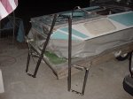
The next few pictures show you the base framework of the new drive system stand. This is a view form the port rear of
the craft during a temporary test fit. |

|
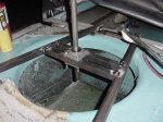
There is a "box" frame in each corner of the rear deck. I have welded two tabs on each frame so I can thru-bolt to the
wooden framework inside the rear "transom". There is also a piece of angle welded to the forward tube of the box frame with bolts going thru the wooden stringer that goes across the rear deck. |

|
Here is a picture of the incomplete forward end of the stand. I will be welding a piece of angle across these tubes so
I can secure the front of the stand. I will make the piece of angle a bit wider than the front tube so I can attach the guard braces to it later. |

|
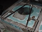
A view looking down on the rear deck. Notice the offset of the fan duct. This was in the original plans
to help compensate for the effects of torque on the craft from the engine and prop. |
|
This is the stand base ready for the next step in the assembly process. |
|
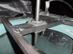
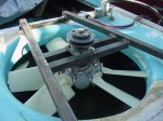
I cut and drilled the two fan bearing cross members so I could locate the position of the fan. I marked the main rails
and tack welded them in. Here I am rechecking the position of the shaft and bearings. |
|
Another view of the fan bearing cross members, shaft and bearings after I tack welded them together. |
|
After I test fit the fan and the pulley I realized the pulley would be higher than I wanted. I cut out the
tack welds and added a 3/4" piece of angle to the end of the cross members and welded the piece of angle to the bottom of the main rails. |

|
Now the fan bushing sits tight up against the bearing and the trailing edge of the blades are right at the bottom edge of the
duct. The pulley sits a little lower now and I think it will fit a little bit better under the engine. |
|
I have the two forward vertical prop shaft frame supports tack welded in place. The board is clamped
between them to hold them so I don't break the tack welds. |

|
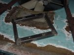
This is the prop shaft frame. It will be welded on top of the four vertical tubes and will support the
pillow blocks. The bolt hole bushings have also been welded in place. |
|