I got the four vertical tubes and the prop shaft frame tack welded together. Getting it lined up
was a bit tough but I finally got it after a lot of pushing, pulling and bracing while I did all the tack welds. |

|
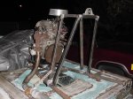
Here is a view from the rear corner. You can see the overall positioning of everything here. I set a
bearing on top of the rail so I could measure for the prop tip clearance. I came out just where I wanted it. |
|
Another rear angle view. Here you can see the exhaust system. It is very close to where it will
actually be when its mounted properly. |
|
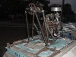
This is a nice side view. The only thing above the stand will be the air cleaner. The engine has come
out lower than before so my CoG has dropped at least an inch or two. |

|
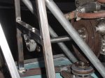
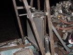
I tack welded in the thrust braces and the drive shaft bearing crossbar. |
|
Detail view of the drive shaft, bearing and crossbar. The radiator is going to be able to mount easily
behind the shaft. |
|
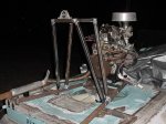
This is the overall view of the stand. I have set the prop shaft in the bearings with the fan pulley, drive
sprocket and one of the hub clamping sprockets to check the overall fit. |
|
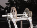
Detail view of the top of the stand showing the prop shaft, fan pulley, drive sprocket and one of the sprockets
that will be clamped to the prop hub. |
|
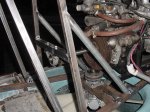
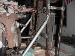
This is looking from slightly behind the stand and from the starboard side. The radiator brackets are
almost completed and they seem to be adding a little extra support between the fore and aft tubes. |
|
Here is a view from the port front. The upper rad hose will need to pass through the middle of the chain
loop and bend slightly under the distributor. The fan drive belt will pass easily underneath the rad. |
|
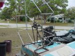
I finally got the guard started. I opted for an octagonal frame instead of round and it was so much easier
this time. I have both hoops made and a few braces installed. |

|
You can see several spreader bars between the hoops and some braces tying the front hoop to the engine
stand. The guard will be permanently attached to the stand. |
|