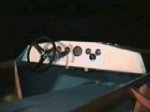
A view of the dash panel with the cutout for the gauges and the steering shaft wedge with the wear plate.
The wear plate is 3/16 aluminum and acts as the load bearing surface also. There is another plate on a support bar under the deck. Notice the PVC tubes under the dash for the skirt dump
control lines. |

|
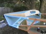
The foredeck area is is now painted and ready for the steering gear and electrical system to be installed. |
|
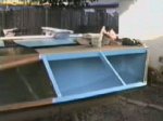
Looking aft at the dash panel, deck stringers and gauge cutout. Notice the shelf at the bottom center of
the cutout. I will mount a ground buss and a terminal strip here. |

|
Another view of the foredeck area. Notice the guide tubes for the skirt dump controls and the forward
steering shaft support bar. |
|
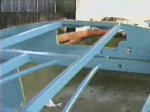
A view of the painted port aft flotation compartment and all the junk that accumulates during the day
while I'm working. |
|
Another view of the flotation compartment with the prop guard and cleat mounting board installed. Also
shows the fan duct with the idler pulley clearance cutout and the wiring harness PVC tubing. |

|
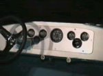
This is a closeup of the gauge panel. The res is low due to camcorder capture. Again, you can see the
pvc for the skirt dump control lines. |
|
This is an overall view of the dash layout with the new gauges mounted in the painted aluminum gauge panel. |
|
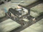
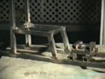
This is the buildup on the main engine stand rails to support the fan shaft and bearings. The
main rails are spaced to match the C/L dimension of the engine mounting bolts. There is a 2.25" diameter peice of auto exhaust pipe welded in the center to help the stabilitiy of the buildup.
|
|
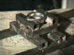
Another view of the fan shaft and bearing support with the bearing flangette sitting on top. I will drill
thru the square tubes and install compression tubes for the flangette clamping bolts. |
|
This is the raised engine set in position on the main frame rails aft of the fan bearing support. The 90
degree fan pulleys are clamped in position to check run of the belt. The verticle prop supports will be attached to the left of the upper horizontal rails. |

|
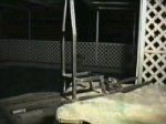
This is a view from the rear of the engine platform. Nothing has been welded to the main rails yet.
This was a locating and positioning session. The engine rails are 6" above the main rails. |
|
This is a closeup of the engine platform, horizontal rails and vertical rails welded into position just behind
the fan bearing mount. |
|
This is a little blurry but gives you a general view of the engine, prop and fan stand looking at it from a rear
corner. |
|
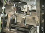
This is the first real test fit of the engine. It is actually sitting on the adjustable
mounting bolts. You can see the clamps holding the idler pulley shaft in place while I checked the belt alignment. |

|
This is a closeup of the adjustable mounting bolts. Using the bolts the engine can be lifted
to tighten and align the fan belt. |
|
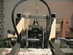
Here is a closeup of the fan bearings, shaft and pulley mounted in place for its test fit. |

|
Not a great pic, but its an overall view of the engine and stand setup. The engine will ride
about 7 inches higher than the vertical shaft engine called for in the plans. |

|
Finally, a scanned photo that's a little sharper than the others. This is the overall view with the prop shaft, bearings, pulleys
and belts in place. Still waiting for the prop belt idler pulley to arrive and then the engine stand will be complete. |

|

|
The Kohler engine stand is now complete and ready to install on the rear deck!I hope you continue to look
through the final phases of my construction photos and then continue on to view the pictures of my maiden voyage as well as all my other adventures! Happy Hovering! |