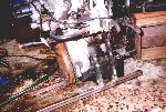
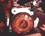
This is the starboard engine support just after all the pieces were cut, welded and drilled. |

|
This is the starboard engine support again but attached to the engine. Notice the rail has yet to be
trimmed to length. |
|
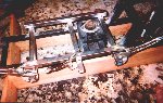
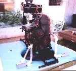
Here is the first fit and welding of the cross members and the engine mount rails. |
|
The cross members, rails and rubber engine mounts look pretty good after being painted. |

|
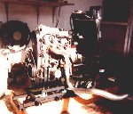
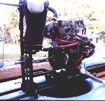
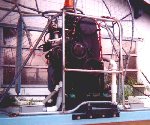
The engine and Radiator finally get test fitted to the stand. Everything is coming together
extremely well! |
|
A top view looking at the radiator and overflow tank mounting. |
|
I made these two starter mounting brackets from 1/2" aluminum plate. They should be plenty strong.
|
|
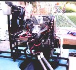
I tried to get a good close-up of the business side of the engine. You can easily see the VW carb and
intake adapter. The engine mounting brackets are also partially visible. |

|
Finally! She's all bolted back on the rear deck wired and plumbed!!! |
|
Another angled shot from the rear and side showing more of the radiator installation and plumbing. |
|
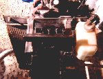
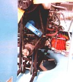
Here is a shot of the starboard side of the GEO installation. You can easily see the VW carb and the intake
adapter I fabricated. The red hoses are the intake preheater hoses. |
|
This is the view from the port side. Here you can see the rubber engine mounts, the main wiring harness
bundle, the drive shaft bearing with the fan pulley behind it and the exhaust pipe adapter on the manifold. |

|
This the reworked guard with all the new tubing welded in place. |

|
The reworked guard installed and a small section of the screen has been put in place. |

|
A straight on side view of the new part of the guard. |
|
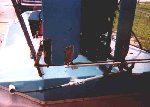
A low front shot. You can see the battery cable conduit on the left (as you face the picture) and the main
harness conduit on the right as well as the forward main drive stand attachment to the hull. |
|
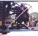
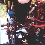
This is looking at the business end of the completed drive gear
installation. You can see the fan drive pulley and idler pulleys toward the bottom. The chain drive sprocket is just aft of the
fan pulley, the blue device between the two chain sprockets is the auto tensioner. The pulley behind the prop is the original belt pulley that is now now only used as a prop hub adapter. |

|
A rear view of the craft showing the steering system upgrade. This is a regular boat steering system
typically used for an outboard motor setup. The cable is run through the tubing to prevent water from back flowing into the hull. The cable end is attached to an adapter plate on the rudder
crossbar. |
|
A pretty good close-up of the chain drive system as well as the fan drive pulley and idler pulleys. |
|
Another view of the drive system. The aft drive shaft bearing is just forward of the fan drive pulley.
|
|